
To identify electronic components, start with the board label, part marking, package shape, polarity mark, and circuit location. Then confirm the value and pinout against a datasheet before replacing anything. Do not guess on fuses, capacitors, power parts, lithium batteries, or mains-powered circuits.
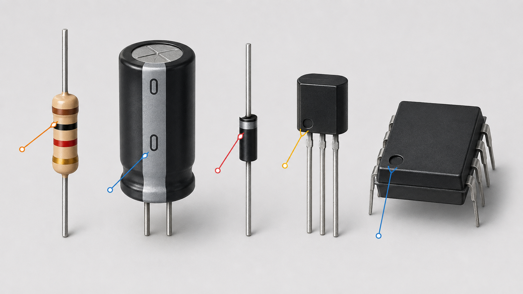
This guide is for naming a part and deciding whether a replacement is safe to match. It is not a full measurement lesson, soldering lesson, schematic-reading lesson, or complete troubleshooting process.
If the device is still powered, getting hot, swollen, wet, smoky, or connected to mains power, stop before touching the board. Component identification starts after the device is safely disconnected and the risk level is clear.
What This Guide Covers
Component identification means answering five questions before you order or install a part:
- What type of component is it?
- What value or part number does it have?
- Is it polarized?
- What package, footprint, lead spacing, or pinout does it use?
- Can the replacement safely handle the same voltage, current, heat, and circuit role?
That last question matters. Two parts can look identical and still behave differently. A SOT23 package, for example, can hold a diode, a transistor, a MOSFET, an ESD protection part, or a regulator. Shape is only a clue.
Safety Boundary Before You Inspect A Board
Work only on an unpowered device. Disconnect the charger, adapter, mains plug, and removable battery if the design allows it. Pressing the power button after unplugging may discharge some low-voltage circuits, but it does not prove that every capacitor is safe.
Capacitors can retain stored energy. Nichicon’s aluminum electrolytic capacitor guidance says capacitors should be discharged with a resistor and polarity should be confirmed before installation. If you do not know how to discharge a capacitor safely, stop there.
Use ESD protection when handling exposed boards and semiconductor parts. The EOS/ESD Association explains that grounded work surfaces and wrist straps help keep people and parts at the same electrical potential, but it also warns that wrist straps must not be used when the operator may be exposed to circuits of 250 V or higher.
Do not open or continue inspecting a device that has any of these signs:
- Swollen lithium battery.
- Burning smell, smoke, or charred board area.
- Wet board, corrosion, or liquid residue.
- Cracked battery pack or punctured cell.
- Repeated blown fuse.
- Power-supply primary side, inverter section, printer high-voltage area, or mains input section.
Those are diagnosis jobs, not simple identification jobs.
The Six-Step Component Identification Workflow
Use this sequence before removing anything. It keeps the part, board location, and orientation connected.
- Photograph the board first. Take one wide photo and one close photo of the component. Include nearby labels and connectors.
- Read the board reference designator. Markings like R23, C14, D5, Q7, U2, F1, L3, J1, and SW1 often tell you the component family.
- Read the body marking. Look for a printed value, color band, top code, logo, polarity stripe, pin-1 dot, notch, or date/lot code.
- Identify the package. Through-hole, SMD chip, SOT23, SOIC, QFN, BGA, radial capacitor, axial diode, and cartridge fuse are not interchangeable shapes.
- Confirm polarity and pinout. Dots, notches, stripes, beveled edges, long leads, and board symbols help, but the datasheet is the final check.
- Match the replacement by function and rating. Value alone is not enough. Match electrical limits, package, lead layout, temperature rating, safety role, and circuit function.
Common Board Labels And What They Usually Mean
Reference designators are helpful, but they are not universal. Treat them as a starting point.
| Board label | Likely part | Identification risk |
|---|---|---|
| R | Resistor | Could be a jumper, sense resistor, fusible resistor, or resistor network. |
| C | Capacitor | Polarity, voltage rating, ESR, ripple current, and dielectric type may matter. |
| D or LED | Diode or LED | Cathode direction and diode type must be confirmed. |
| Q | Transistor or MOSFET | Same package can have different pinouts and ratings. |
| U or IC | Integrated circuit | Top marks can be shortened. Use a marking lookup or datasheet. |
| F | Fuse | Never bridge it. Match current, voltage, speed, interrupt rating, package, and approvals. |
| L | Inductor or coil | Current rating, DC resistance, shielding, and physical size affect behavior. |
| J, CN, or CON | Connector | Pitch, pin count, keying, and current rating matter. |
How To Identify Resistors
Through-hole resistors often use color bands. SMD resistors may use a printed code such as 102 for 1,000 ohms, but very small parts may have no useful marking at all. Vishay provides a resistor color code calculator that is useful when the bands are clear.
For replacement, match resistance, tolerance, power rating, package size, and temperature behavior. Do not replace a flameproof or fusible resistor with an ordinary resistor just because the ohm value matches.
A resistor that measures wrong in circuit may be affected by parallel paths. If the value matters and the reading looks strange, the part may need to be lifted or tested in a controlled way. That step belongs in a measurement workflow, so use the multimeter guide for the measuring method.
How To Identify Capacitors
Capacitors can be ceramic, film, aluminum electrolytic, polymer, or tantalum. The value may be printed directly, encoded with three digits, or not marked at all.
Common ceramic examples:
- 104 means 10 followed by four zeros in picofarads, or 100 nF.
- 223 means 22 followed by three zeros in picofarads, or 22 nF.
- 472 means 47 followed by two zeros in picofarads, or 4.7 nF.
Electrolytic capacitors usually show capacitance, voltage, temperature, and polarity on the sleeve. The stripe normally marks the negative side on many radial aluminum electrolytic capacitors, but always compare the sleeve, the board mark, and the datasheet.
Replacement is not only capacitance. Match capacitance, voltage rating, polarity, temperature rating, ESR, ripple current, package diameter, height, and lead spacing. On switching power supplies, low-ESR and ripple-current requirements can matter as much as capacitance.
Never install a polarized capacitor backwards. Nichicon’s application guidance states that aluminum electrolytic capacitors are polarized and should not receive reverse voltage or AC voltage. It also warns that a capacitor used beyond specification may vent, catch fire, or be damaged.
How To Identify Diodes And LEDs
A diode has an anode and a cathode. Many through-hole signal and rectifier diodes use a band to mark the cathode end. LEDs often have a flat side or lead-length clue, but lead length alone is not reliable after trimming or removal.
Identify the diode type before replacing it:
- Rectifier diode for converting or steering power.
- Schottky diode for low forward voltage and fast switching.
- Zener diode for voltage reference or clamping.
- TVS diode for surge protection.
- LED for indication or lighting.
Match package, cathode direction, current rating, reverse voltage, forward voltage, speed, and special function. A Zener, TVS, Schottky, and ordinary signal diode are not safe swaps just because the package looks similar.
How To Identify Transistors, MOSFETs, And Regulators
Small three-pin parts are easy to misread. A SOT23 package can contain several different component families. The top code may be shortened and may not equal the full part number.
Use the board label, top mark, manufacturer logo, circuit location, and package together. Then confirm the part with a datasheet or manufacturer marking tool such as the Texas Instruments part marking lookup when the part appears to be from that manufacturer.
For bipolar transistors, match NPN or PNP type, collector current, voltage rating, gain range, package, and pinout. For MOSFETs, match N-channel or P-channel type, drain-source voltage, current, RDS(on), gate threshold, gate charge, package, thermal path, and pinout.
Do not assume that every TO-92, SOT23, or TO-220 part has the same pin order. It does not.
How To Identify ICs
Integrated circuits are usually identified from the top marking, package, pin count, logo, and circuit role. A dot, notch, bevel, or molded mark can indicate pin 1. Some packages also use a chamfered edge or printed orientation mark.
Before replacing an IC, confirm the full part number, package suffix, pin 1 orientation, supply voltage, function, thermal pad requirements, and firmware or programming needs. Some ICs are blank, custom-marked, programmed, locked, or paired to another board. In those cases, a generic replacement may not work at all.
BGA, QFN, and tiny leadless packages are not beginner replacement parts. If the pads are hidden or the package needs controlled hot-air, preheating, or reballing, stop and move to professional diagnosis.
How To Identify Fuses And Protection Parts
A fuse is a safety component, not just a wire that melts. Littelfuse’s Fuseology material treats fuse selection as a design decision involving characteristics, selection factors, standards, and certifications.
Match all of these before replacing a fuse:
- Current rating.
- Voltage rating, including AC or DC rating.
- Fast-acting or time-delay behavior.
- Interrupting or breaking capacity.
- Physical package and holder fit.
- Agency approvals and safety category when present.
Never bridge a blown fuse with wire, foil, solder, or a higher-rated fuse. A blown fuse is often a symptom of a downstream short. Replacing it without finding the cause can turn a repairable fault into board damage or a fire risk.
How To Identify Inductors, Coils, And Transformers
Inductors may use printed values, color bands, molded shapes, or no obvious marking. In power circuits, the key details are inductance, current rating, saturation current, DC resistance, shielding, package size, and temperature behavior.
Transformers and coils are even more specific. Pinout, winding ratio, insulation, current rating, and safety isolation matter. Do not replace a mains transformer, inverter transformer, or power-supply magnetic part by appearance alone.
Safe Testing Limits
Safe beginner checks are visual and low energy. Photograph the board, inspect for broken parts, compare reference labels, read markings with good light, and check orientation before removal.
Unpowered resistance, continuity, and diode-mode checks can help in simple cases, but in-circuit readings can mislead because nearby parts create alternate paths. A low reading does not always mean that the part you touched is shorted.
Do not live-test mains circuits, power-supply primary sections, inverter boards, microwave-style high-voltage circuits, printer high-voltage supplies, charger internals, lithium battery packs, or wet boards. If voltage must be measured, that belongs under controlled troubleshooting with the right meter category, probes, isolation, and experience.
For measurement details, use the how to use a multimeter guide. For signal flow and schematic symbols, use the schematics guide. This page is only the identification and replacement-matching layer.
Replacement Compatibility Checklist
The best replacement is the exact same manufacturer part number from a reliable source. When that is not available, compare the datasheet line by line.
Check these before installing a substitute:
- Same component type and circuit function.
- Same value or approved value range.
- Equal or better voltage and current ratings where applicable.
- Correct polarity and pinout.
- Same package, footprint, height, and lead spacing.
- Suitable tolerance, temperature rating, ripple current, ESR, speed, or timing behavior.
- Same safety role, such as fuse type, flameproof resistor, X or Y safety capacitor, TVS diode, or isolation part.
- No evidence that the original part failed because of another unresolved fault.
If one of those points cannot be confirmed, write it down as unknown instead of guessing.
When Professional Diagnosis Is The Safer Choice
Stop before replacement if any of these apply:
- The marking is burned off and no schematic or matching board area is available.
- The same fuse blows again.
- A capacitor vented, leaked, swelled, or was installed backwards.
- The board has liquid corrosion, lifted pads, cracked traces, or carbonized material.
- The part is connected to mains input, a charger primary side, inverter output, or a high-voltage printer section.
- The part is a BGA, leadless IC, programmed IC, paired security chip, or battery-management component.
- The device contains a swollen or damaged lithium battery.
- You cannot explain why the original component failed.
A visibly damaged part is often the result, not the cause. Replacing it may only make the next weak point fail.
Quick Examples Of Good And Bad Replacement Thinking
Good: `C47` is a 470 microfarad, 25 V, 105 C low-ESR electrolytic capacitor with the negative stripe facing the marked board side. The replacement has the same capacitance, equal or higher voltage rating, correct diameter, correct height, correct lead spacing, matching polarity, and ripple/ESR ratings suitable for the same power-supply position.
Bad: `C47` is a black cylinder, so any black cylinder that fits the holes should work.
Good: `F1` is a 3.15 A time-delay fuse with a specific voltage rating, package size, and approval marking. The replacement matches those details and the downstream short has been checked.
Bad: The fuse blew, so a larger fuse or wire jumper will keep the device running.
Frequently Asked Questions
Can I identify every component by looking at it?
No. Visual inspection gives clues, not final proof. Many SMD parts use short top codes, shared packages, or no useful marking, so you still need the board label, circuit role, and datasheet.
Can I replace a capacitor with a higher voltage rating?
Sometimes, but only if the capacitance, polarity, ESR, ripple current, temperature rating, size, and lead spacing also fit the circuit. A higher voltage rating alone does not make the part compatible.
Is it safe to replace a blown fuse first?
Not until the likely cause is checked. A fuse opens because too much current flowed, so replacing it without finding the short or overload can create a more dangerous failure.
Why does pinout matter if the package is the same?
The package only tells you the physical body. It does not guarantee the same internal device or pin order. Always confirm the datasheet pinout before installing a transistor, MOSFET, regulator, or IC.
Next Step If You Are Still Unsure
If you only need to name a safe, unpowered part, keep working from the markings, board label, and datasheet. If the device has power, heat, liquid, high voltage, a lithium battery problem, a repeated fuse failure, or unknown damage, stop the DIY path.
For the broader diagnosis sequence, read the electronics troubleshooting guide. For tools and safety boundaries, use the tools and skills hub and the ESD protection guide.
If you want ACJ Electronics to inspect the actual device, use the contact page and include the device model, symptom, clear photos, and anything that happened before the fault appeared.